
Most people, if they have half a brain, will check what wire size is needed to carry a given ampacity before they start hooking up stuff. It’s important if you’re wiring a building and important if you’re wiring electronic equipment. You don’t want things you value to burn down or up.
Unfortunately, an ampacity table, while easy to find with a quick Intertubz search, doesn’t tell the entire story. While researching why a small 2 meter amplifier I recently purchased called for 10 gauge wire “for a short run” or 8 gauge wire “for longer runs” for a maximum current draw of 345 watts, I kept finding various notes on solid vs. stranded wire and “current drop”.
So I did my own research, and I feel pretty confident with what I’m going to present. Think of these as rules of thumb, and remember you should always check the numbers yourselves.
In 3 bullet points:
- Resistance in ohms per 1000′ of wire generally decreases as the wire gauge goes up and the wire goes from a single solid conductor to multiple strands. Not always, but generally.
- When sizing wire for a given voltage draw, normal ampacity tables have simplified things down to the point where their accuracy needs to be in question. Compare this table with the one from the previous bullet point. This table uses a large amount of fudge factor, so based on something in the next bullet point, you may be buying a lot more expensive copper than you need. Or not. You have to do the math. Every time.
- The correct way to size your wire is to look at the voltage loss for the particular type of wire and its application. The “acceptable range” for current drop is generally said to be 3-4%. So once you know the volts and amps that need to be delivered to a device, it’s relatively simple to use this formula to determine if a given wire will work over a specified run. That formula is:
((Rw * 2l * .001) + 2k) * A = Vd
where:
Rw = the 1,000 foot resistive value
l = Overall length of the cable assembly (include your connectors)
k = resistive value for one fuse and its holder, conservatively 0.002 ohms
A = Peak current draw in amps
Vd = Cable assembly voltage drop(This formula, along with a master class on all varieties of wiring for amateur radio, can be found at the web site of K0BG. The entire site is a great resource, not just for the mobile operators it’s aimed at, but all hams.)
Let’s put this into practice using my situation as the example.
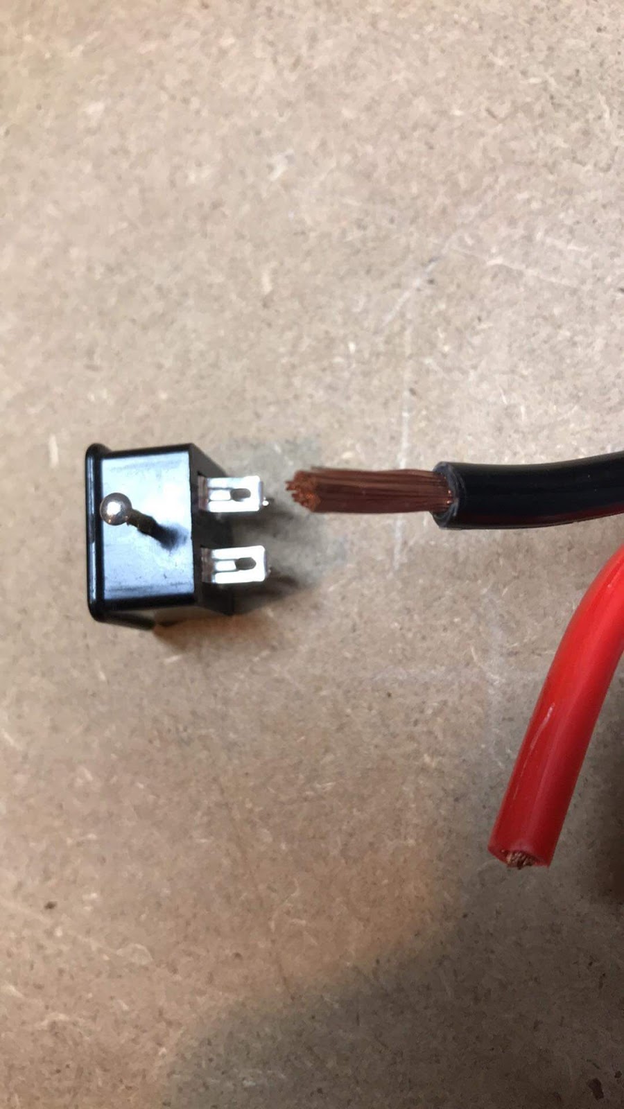
As noted before, the product manual says to use 8 or 10 gauge wire. The problem, as I originally saw it, was with the connector on the amplifier. It’s known as a Clinch-Jones connector, but a picture is worth a thousand words.:
 |
| Click to embigginate |
For reference, that wire is 10 gauge. The lugs measure 0.143″/3.64 mm, and there are 4 of them. You’re seeing the two in the vertical orientation; there are two more that are horizontal. One set positive, one negative, and you need to connect your wiring to both lugs in a pair.
Can this be done? Sure, but I think you’re running a sizeable risk of damaging the connector with the necessary heat. I considered using quick disconnects, but I can’t find any that fit 10 gauge wire and lugs that small.
So I started looking at it from the standpoint of “Do I really need that much wire for 345 watts?” Look at the power cord for a 1500 watt electric heater – that wire is nowhere near 10 gauge – it’s more like 16 or 18 gauge.
So let’s put all down. I need to provide 13.8 volts DC @ 22 amps, per the amplifier manual. A 3% voltage drop is 0.414 volts; a 4% drop is 0.552 volts. Our acceptable range for Vd: 0.414 – 0.552. I want to use 200oC silicone insulated all-copper wire.
An immediate problem popped up. The wire vendor I’m looking at doesn’t provide resistance values. I’m using values from here, using the closest wire they have to the 14 gauge I’m considering using. (I’d use their wire if I could, if only because they provide full information, but they appear to be an industrial supplier.) The required length is 6′ and I’m using 22 amps as called for in the manual.
For 14 gauge wire, it’s
((2.99 * 2(6) * .001) + 2(.002) * 22 = Vd, or 0.88 – not nearly good enough.
For 12 gauge wire, it’s
((1.6 * 2(6) * .001) + 2(.002) * 22 = Vd, or 0.51 – We have a winner!
Of course, I could give the 10 gauge a try, just to see
((1.1 * 2(6) * .001) + 2(.002) * 22 = Vd, or 0.38 – at the other end of the acceptable range.
So 12 gauge stranded copper it will be. Now for how I’m going to make the connections – back to research!
Edit, 4/15/2019: Once again, something generated a lot of messed up HTML and the math for the wire gauges I looked at was blanked out. Fixed it.
In the comments, B points out that this is actually voltage drop, and he’s correct. I used the term “current drop” because that is what the majority of links I found called it and I wanted to stay with the common term, even if inaccurate. But he’s right, and after thinking about it I’m going to change it to the correct terminology in the title and the bullet points. Accuracy is more important than keeping Google’s search results happy. I’m leaving it in the body where I refer to how this information was originally found.
Edit, 4/18/2019:You might also wish to read “Current drop vs. voltage drop“.

Voltage drop. Current is a factor of voltage and resistance.
Thanks, B. I've thought on it some, and even though the term "current drop" is what led me to the information, in reality voltage drop we're calculating. I'll fix it in the title, but I'm going to leave it where I talk about how I found it. Thanks for pushing me to rethink my original stance on it.
Never heard the term "current drop" before. Seems rather misleading what with all currents into and out of a node being equal and such.
I've been doing some more reading, and it's a confusing thing for me. I've found articles that, like B, point out it's not really current drop but voltage drop. I find others that discuss current drop vs. voltage drop, and at this particular point in time I have to admit not getting the gist of the thing. Then there are the articles on current drop.
I get the difference between voltage (measured in volts) and current (measured in amps), but there is a relationship between the two. As they put it at https://www.diffen.com/difference/Current_vs_Voltage "Voltage is the cause and current is the effect." And then every time I think I have this stuff, something happens and I don't.
Seems to me like a great reason to work in watts.
"Seems to me like a great reason to work in watts." It gets more confusing when your load has some reactance; then you gotta think about lead and lag of voltage and current AND, luckily, I don't have to because ignorance is bliss. I'm just gonna assume the load is purely resistive.
A non-tech friend wanted to know the difference 'twixt voltage and current. I replied that a wire is like a garden hose wherein voltage is water pressure and current is gallons per minute. Didn't help…
I'm not to go that far off into Theory World. Reactance will just have to suck it up, so to speak.
I've kept looking at this, and I've found one thing that makes it a lot clearer, at least in terms of "Do I need to be concerned about voltage, amperage or watts?" I've found that in AC wiring, amperage is the thing you key on. In DC, it's voltage drop.
I may just leave it there.